TechShop
Thursday, 10 April 2014
Recently I joined TechShop and started taking the classes they offer in the use of the tools (which are required in order to use those tools).
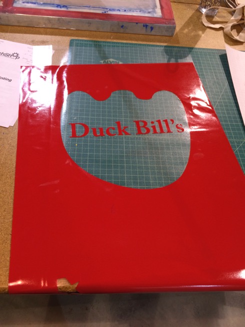
I made the kids a t-shirt and tote bag for their fake restaurant — DuckBill’s — in the silk screening class:

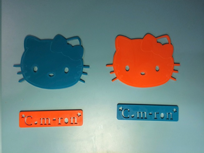
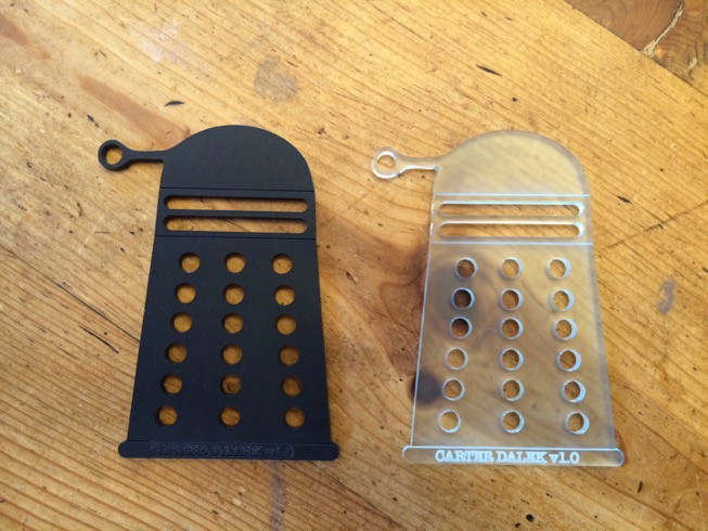
And some acrylic trinkets on the laser cutter:
I still have lots to learn but I can see a multitude of projects in my head that access to all these tools opens up: including a proper case for that badminton scoreboard.
I made the kids a t-shirt and tote bag for their fake restaurant — DuckBill’s — in the silk screening class:
And some acrylic trinkets on the laser cutter:
I still have lots to learn but I can see a multitude of projects in my head that access to all these tools opens up: including a proper case for that badminton scoreboard.
Badminton Scoreboard IV: Working!
Tuesday, 18 March 2014
Last time I had just sent the boards for fabrication on February 22nd. I got them back on March 7th:
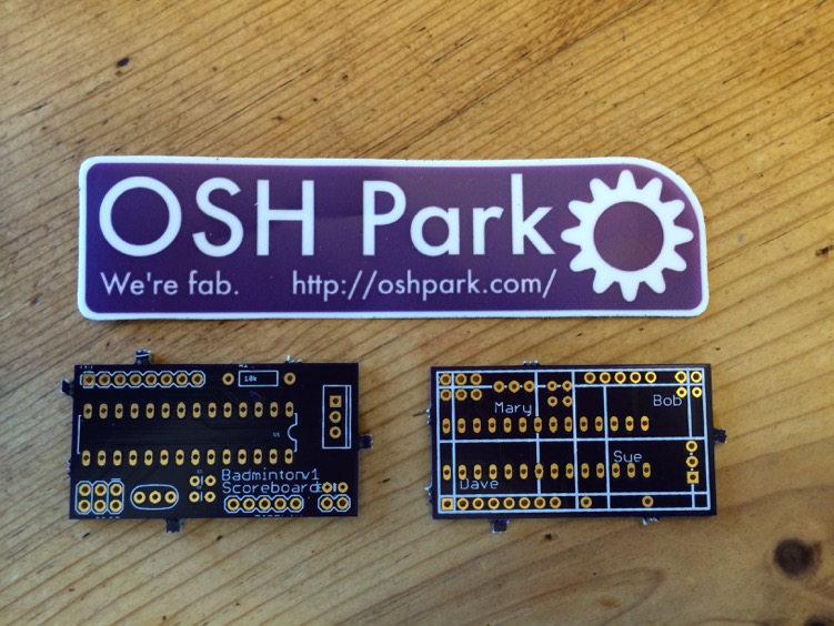
They look amazing. I find it hard to believe how easy, cheap ($9.10 for 3, shipped), and quick it was to go from the Sparkfun Eagle tutorials to a physical board in my hands.
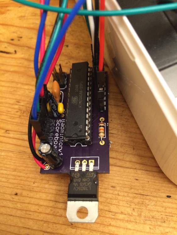
I should have left room on the board to fold over the bigger caps, but other than that putting together one of the boards went pretty well:
It didn’t work though, and after a minor panic I realized I had switched the 5V and GND pins for the radio when creating the schematic. Once I switched the jumper cables attached to them around it worked!
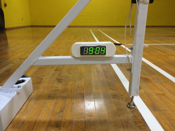
Next I hacked a bandaid box as a case. It works okay for now, but it was hard to cut and so the edges are pretty rough. I’ve joined my local TechShop, so I plan to make a better case for it at some point.
Here’s the initial assembly in the case:
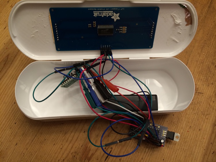
You can see what an awful mess of jumper cables I had. I realized at this point that I should have used male connectors on the board for the radio and display, not female. I have a solder sucker but no braid, so it took me ages to get them swapped, and I did something bad to the radio 5V connection in the process. Rather than go through the pain of taking the male connector off, after spending so long to get it on there, I took the easy way out and just used the 5V pin on the ICSP header. I will now for next time.
To clean up the jumper wire mess I tried making a ribbon cable using standard male connector pins, with heat shrink around each connection, but I could tell it wasn’t going to hold up to use. It also looked like crap.
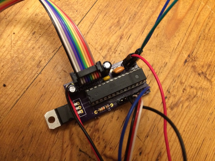
I didn’t have any pre-made 1x5 cables but I realized I did have 2x5 cables, and who cares if you don’t happen to actually connect one row of the pins to anything? One of those cleaned up the display connection nicely.
The radio was more problematic since I had screwed up the 5V and GND connections—if they’d been right I could have plugged the radio directly into a female socket on the board as originally intended. Instead I used a 1x3 servo cable and 3 jumper wires. Not ideal, but much better than the mess I had before.
This left me with:
The scoreboard worked pretty much perfectly, except that sometimes if you released the button too quickly it wouldn’t register the button press. That meant we ended up having to look at the scoreboard while pressing the key to make sure it registered. By the end of the evening it was clear that adding a beep when it recognized a button press would make it more user friendly.
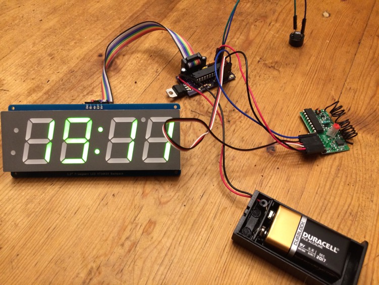
And here it is in action (taken before I added the buzzer):
They look amazing. I find it hard to believe how easy, cheap ($9.10 for 3, shipped), and quick it was to go from the Sparkfun Eagle tutorials to a physical board in my hands.
Assembly
I should have left room on the board to fold over the bigger caps, but other than that putting together one of the boards went pretty well:
It didn’t work though, and after a minor panic I realized I had switched the 5V and GND pins for the radio when creating the schematic. Once I switched the jumper cables attached to them around it worked!
Next I hacked a bandaid box as a case. It works okay for now, but it was hard to cut and so the edges are pretty rough. I’ve joined my local TechShop, so I plan to make a better case for it at some point.
Here’s the initial assembly in the case:
You can see what an awful mess of jumper cables I had. I realized at this point that I should have used male connectors on the board for the radio and display, not female. I have a solder sucker but no braid, so it took me ages to get them swapped, and I did something bad to the radio 5V connection in the process. Rather than go through the pain of taking the male connector off, after spending so long to get it on there, I took the easy way out and just used the 5V pin on the ICSP header. I will now for next time.
To clean up the jumper wire mess I tried making a ribbon cable using standard male connector pins, with heat shrink around each connection, but I could tell it wasn’t going to hold up to use. It also looked like crap.
I didn’t have any pre-made 1x5 cables but I realized I did have 2x5 cables, and who cares if you don’t happen to actually connect one row of the pins to anything? One of those cleaned up the display connection nicely.
The radio was more problematic since I had screwed up the 5V and GND connections—if they’d been right I could have plugged the radio directly into a female socket on the board as originally intended. Instead I used a 1x3 servo cable and 3 jumper wires. Not ideal, but much better than the mess I had before.
This left me with:
Field Test
I took the roughly assembled version to our next badminton evening to try it out. The range of the key fobs was much greater than it had been on the breadboard: they worked from every corner of the gym. I suspect the difference is due to interference from the breadboard’s many connections, but whatever it was the real-world range with the custom board meant the key fobs were actually going to be practical.The scoreboard worked pretty much perfectly, except that sometimes if you released the button too quickly it wouldn’t register the button press. That meant we ended up having to look at the scoreboard while pressing the key to make sure it registered. By the end of the evening it was clear that adding a beep when it recognized a button press would make it more user friendly.
Adding a Buzzer
A piezo buzzer ought to do the job just fine, but I hadn’t broken out any of the other digital I/O pins. However the ICSP header has connections to MOSI, MISO and SCK. These correspond to digital pins 11, 12 and 13 of the Arduino respectively, so I was able to hook up the buzzer between SCK and GND and add a tone() call for D13. It seems like it will be loud enough, but I won’t know until we play next if it really is.Updating the Firmware
I updated the code to add the beep then tried to upload it using my AVRISP mkii, via the File/Upload Using Programmer menu item in the Arduino IDE. It kept failing with a “bad AVRISPmkII connection status: MOSI fail” error. It took me a really long time to figure out why: I probed the pins, double checked the schematic, compared it to a SparkFun arduino clone design, asked a question on the Electronics Stack Exchange and got nowhere. Then, a week later as I was redoing the cables I noticed a solder bridge between MOSI and GND on the underside of the board, where I’d soldered the ICSP header pins. I fixed the bridge and it started working. I can’t believe I didn’t find that earlier!Fin
Here’s the final state of the connections, including the buzzer:And here it is in action (taken before I added the buzzer):
Lessons Learned
- Get the schematic right!
- Allow more room around the outside so the lettering isn’t chopped off.
- Check for solder bridges when things don’t work.
- Make room for strain relief for the battery power connection cables.
- Make room for mounting holes.
- Make room for bending capacitors flat to the board.
- Think harder about whether male or female connectors are what’s needed before soldering them.
Badminton Scoreboard III: PCB
Saturday, 22 February 2014
Now that I got it working with a bare ATmega168, the next logical step is clearly to create a custom circuit board for the Badminton Scoreboard.
I followed along with SparkFun’s excellent tutorials on setting up Eagle and using its schematic and board layout tools. For getting the PCB created, one of the places SparkFun recommended was OSH Park. OSH Park lets you upload an Eagle board file, so you don’t need to generate Gerber files. Their site gives you a nice preview of what the board will look like, so you can check out the solder masks and your silkscreening before committing to an order. They charge $5/square inch for 3 boards, including shipping, which seems pretty reasonable to me.
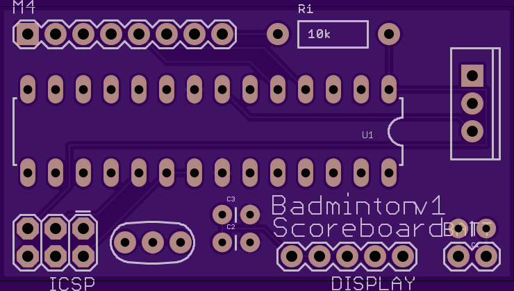
Here’s what I came up with:
The top:
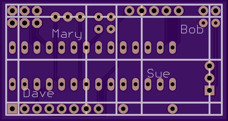
and the bottom, which is supposed to look like a bit like a badminton court (not to scale, as I positioned the court lines to avoid the pads as best I could):
I read a few tutorials on bare board Arduinos and never really got a consistent answer on what values to use for the bypass capacitors, so I winged it a bit. I’ve no idea how well the winging went, if I spaced the components out enough, or if I laid the tracks properly, but I should find out when I get the boards back in a couple of weeks.
I followed along with SparkFun’s excellent tutorials on setting up Eagle and using its schematic and board layout tools. For getting the PCB created, one of the places SparkFun recommended was OSH Park. OSH Park lets you upload an Eagle board file, so you don’t need to generate Gerber files. Their site gives you a nice preview of what the board will look like, so you can check out the solder masks and your silkscreening before committing to an order. They charge $5/square inch for 3 boards, including shipping, which seems pretty reasonable to me.
Here’s what I came up with:
The top:
and the bottom, which is supposed to look like a bit like a badminton court (not to scale, as I positioned the court lines to avoid the pads as best I could):
I read a few tutorials on bare board Arduinos and never really got a consistent answer on what values to use for the bypass capacitors, so I winged it a bit. I’ve no idea how well the winging went, if I spaced the components out enough, or if I laid the tracks properly, but I should find out when I get the boards back in a couple of weeks.
Badminton Scoreboard II: Bare
Saturday, 22 February 2014
I managed to find my AVRISP mkII and I had a regulator and resonator and other sundry parts necessary, so I switched the Badminton Scoreboard from an Arduino to a bare ATmega168 on the breadboard, just because I hadn’t tried that before. Getting the Arduino boot loader onto it was easy, using the Arduino IDE. Getting the sketch onto it was unnecessarily complicated: for one, there are out of date instructions out there telling you that you need to edit the Arduino IDE settings file by hand: you don’t any more — you just need to hold down Shift when you press the Upload button, or choose File/Upload Using Programmer; and for two, Upload Using Programmer has a bug, where it will fail if you don’t have any device connected via USB serial, even though you aren’t actually going to program a device over USB serial. I plugged in a Spark Core and it merrily went on it way and used the programmer to get the sketch onto the 168.
So it’s still a rats nest of jumper cables, but no more Arduino board:
So it’s still a rats nest of jumper cables, but no more Arduino board:
Badminton Scoreboard
Sunday, 16 February 2014
My wife and I play badminton every Friday with a couple of friends. We have a great time, but we’re usually so busy chatting as we play that we keep on forgetting the score.
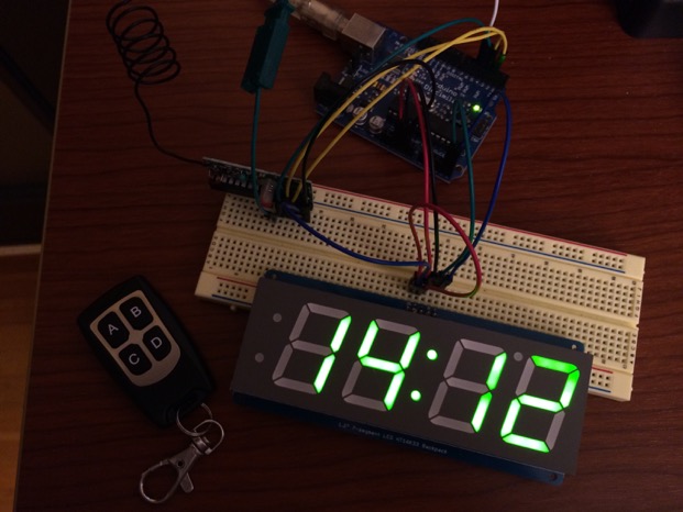
My friend suggested that I ought to make a scoreboard, so here we are. I knew I would need a display, some buttons, and a microcontroller, and that for simplicity the microcontroller should be Arduino-compatible. As I was looking at displays I came across the M4 receiver at Adafruit. It’s a simple RF receiver with four digital output pins; you press a button on a key fob and the matching digital output goes high. The range is supposed to be in the 20-30 feet range, and so it ought to work for my needs. Using key fobs instead of buttons on the scoreboard means I can make the scoreboard smaller too.
Here’s what I’m using:
I wrote an Arduino sketch that watches for the button presses and adjusts the score accordingly. Here are the controls I decided on:
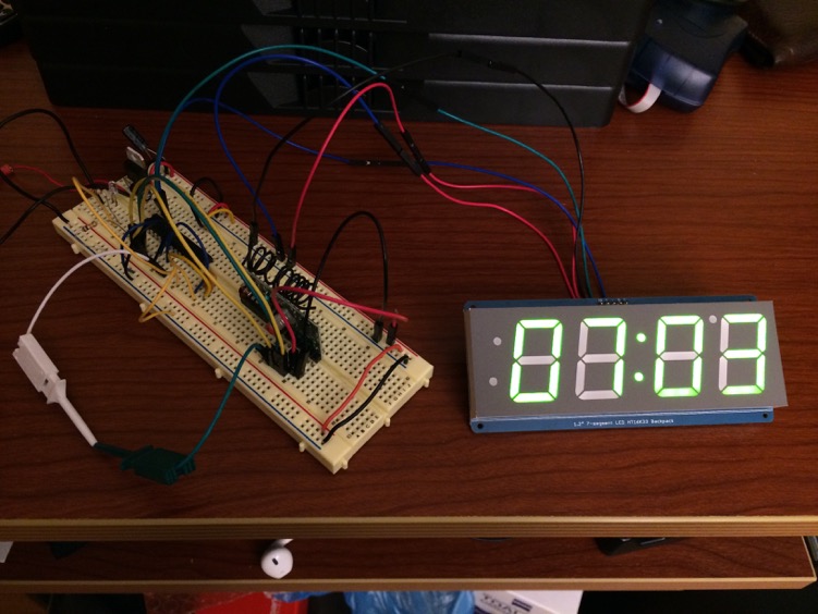
It pretty much worked first time, except that the range of the key fobs in my prototype is only about 18 inches. I noticed that if I remove the display the range improves dramatically, so I think it’s just that I’m powering the Arduino from USB and there’s not enough current to power the receiver and display properly. That shouldn’t be an issue when I switch to a battery pack. [UPDATE: Yup, that’s what it was: the range is fine when powering it from a 4xAA battery pack.]
Here’s the working prototype:
And here’s the sketch:
My friend suggested that I ought to make a scoreboard, so here we are. I knew I would need a display, some buttons, and a microcontroller, and that for simplicity the microcontroller should be Arduino-compatible. As I was looking at displays I came across the M4 receiver at Adafruit. It’s a simple RF receiver with four digital output pins; you press a button on a key fob and the matching digital output goes high. The range is supposed to be in the 20-30 feet range, and so it ought to work for my needs. Using key fobs instead of buttons on the scoreboard means I can make the scoreboard smaller too.
Here’s what I’m using:
- Simple RF M4 Receiver - 315MHz Momentary Type
- Keyfob 4-Button RF Remote Control - 315MHz
- 1.2" 4-Digit 7-Segment Display w/I2C Backpack
- An Arduino Diecimila 168 that I had lying around. (I’ll use something more compact for the finished product.)
I wrote an Arduino sketch that watches for the button presses and adjusts the score accordingly. Here are the controls I decided on:
- Keyfob A button: left player + 1
- Keyfob B button: right player + 1
- Keyfob C button: left player - 1
- Keyfob D button: right player - 1
It pretty much worked first time, except that the range of the key fobs in my prototype is only about 18 inches. I noticed that if I remove the display the range improves dramatically, so I think it’s just that I’m powering the Arduino from USB and there’s not enough current to power the receiver and display properly. That shouldn’t be an issue when I switch to a battery pack. [UPDATE: Yup, that’s what it was: the range is fine when powering it from a 4xAA battery pack.]
Here’s the working prototype:
And here’s the sketch: