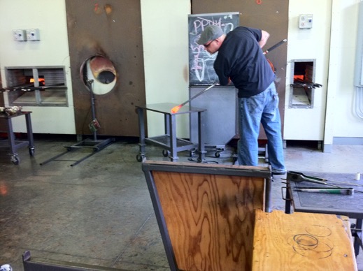
Pittsburgh Glass Center
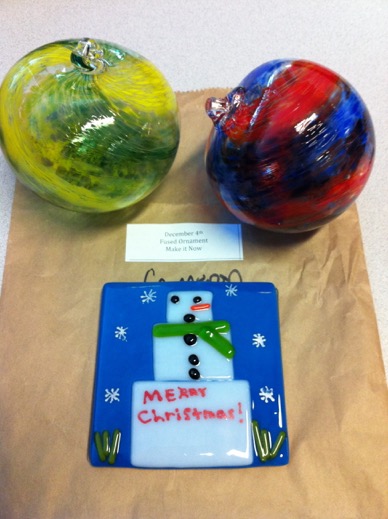
It being such a quick, busy, and kid-friendly, class we didn’t get to be too close to the furnaces or the hot glass, but we did get to pick out our colours and do the blowing. I chose green and yellow, and Cameron chose red and blue. Our teacher did all the hard work but it was still a lot of fun. We’ll be going back for sure.
On the way out we spotted signs for a “fused glass” glass that was also open for kids. This is where you take a glass tile and arrange various pieces of glass mosaic fashion on it, with a dab of glue to hold it in place. They then heat the tiles in the kiln to fuse the glass together. Cameron chose to do a square snowman and it came out perfect!
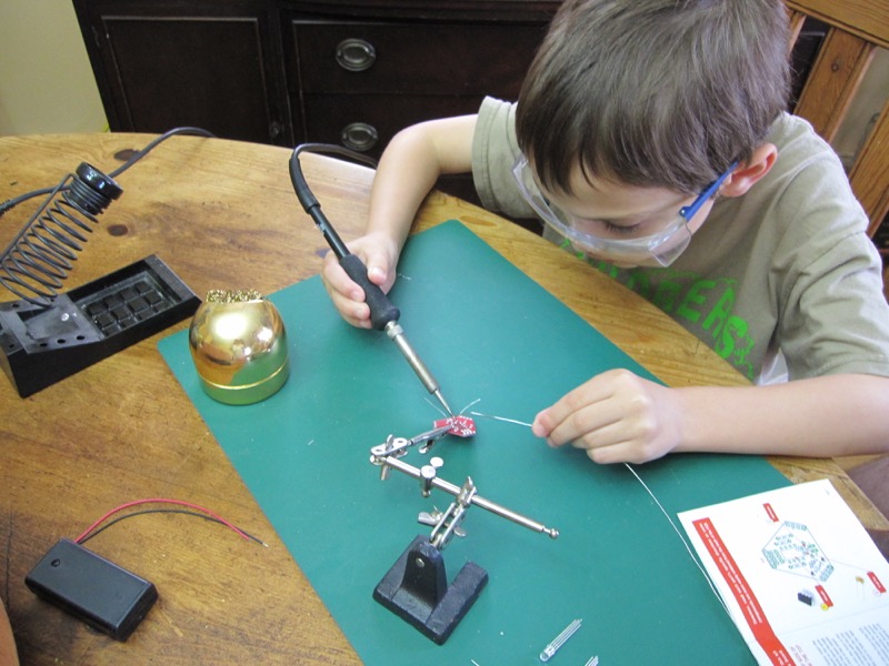
Carter soldering too!
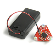
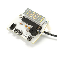
Both of them soldered really well — at least as good as me (not that that would be hard) — and both their kits worked first time. I was particularly impressed with Carter while he soldered the ATtiny95 onto the board: he seemed to know when to clean the tip, when to apply a little dab of extra solder and so on, all without me needing to provide much in the way of guidance.
Maker Faire NYC

We took the kids up to New York to World Maker Faire. It was really hot for September, to the point where Carter had sun stroke, or at least dehydration, on the Saturday, poor kid, so we had to duck out early. He rallyed on Sunday though, and we got to spend the full day there.
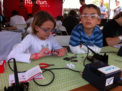
We screen printed t-shirts, Cameron learned to solder with SparkFun, the kids both made casts of their fingers in algir, and we got to take things apart in the deconstruction zone. We also managed to catch up with some Hack Pittsburgers while we were there too.
All in all, it was a really fun weekend, and we’ll definitely go again next year: perhaps to the Detroit one this time.
Notesy

PodBreakout Mini and Teensy
The Teensy and the PodBreakout Mini seem like a match made in much-smaller-iPod-serial-remote-heaven, no? Let’s see…
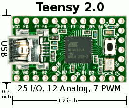
The Teensy 2.0 that Paul sent me is based on the ATMEGA32U4. What makes this chip particularly interesting is that it has a real USB interface, rather than just a serial port with an FTDI chip in front of it doing serial-to-USB. That means you can use it to interact with a host computer as if it were a USB keyboard or mouse, for example. Ladyada has a recent project using this feature of the Teensy. The ATMEGA32U4 also has a regular hardware serial port - that’s going to come in handy in a minute.
The Teensy can be programmed a few different ways. I used the Teensy Loader which comes in versions for OS X, Windows and Linux; I used the Linux version on my 64-bit Ubuntu 9.10 box and it worked fine, barring some minor device file quirkiness in Arduino Serial mode (which Paul tells me seems to be specific to 9.10).
What’s particularly handy for me is that Paul has done a lot of work to integrate the Teensy with the Arduino IDE. Following his instructions I added the Teensy board types very easily using the script he provides.You run the Arduino IDE and the Teensy Loader simultaneously; when you verify a sketch the Teensy Loader detects this and magically uploads the sketch to the Teensy for you; that is you don’t need to (and can’t) use the upload button in the Arduino IDE. It’s pretty slick.
Once I had Blink up and running I set about seeing if my iPodSerial library would work. The usual Arduino
Serial object isn’t of type HardwareSerial for the Teensy so I had to tweak the library to take a HardwareSerial object in its constructor rather than defaulting to Serial. Other than that it was fine. Again Paul has good information about the differences. I think I could probably just #ifdef based on the board type so the same version of the library would work for the Teensy or regular Arduino boards. I haven’t done this yet though, so the version on github won’t currently compile for the Teensy without the aforementioned minor tweaking.I didn’t feel like hooking up a switch so I just tweaked the play/pause example sketch to toggle every few seconds. I tried this and it worked first time! (Well my code didn’t first time, but the electronics all did).
Now by default the Teensy comes configured for 5V, but there are instructions on how to switch it to 3.3V using an optional 3.3V regulator, which Paul had kindly included with my review Teensy. I followed them without any problems.
WIth the board converted I had to tell the Arduino IDE to clock the Teensy at 8MHz instead of 16MHz (it’s not rated for 16MHz when operating at 3.3V although it may work just fine, depending on what you’re doing with it). This was just a matter of editing the
boards.txt file to cut-and-paste an existing section to make a new variant with the slower clock speed (the build_f_cpu line below):myteensy2_ser.name=Teensy 2.0 (USB Serial) - 3.3 volts
myteensy2_ser.upload.protocol=halfkay
myteensy2_ser.upload.maximum_size=32256
myteensy2_ser.upload.speed=38400
myteensy2_ser.upload.disable_flushing=true
myteensy2_ser.upload.avrdude_wrapper=teensy_reboot
myteensy2_ser.build.mcu=atmega32u4
myteensy2_ser.build.f_cpu=8000000L
myteensy2_ser.build.core=teensy_serial
myteensy2_ser.build.post_compile_script=teensy_post_compile
With the Teensy operating at 3.3V you no longer need a Logic Level Converter between it and the iPod, since both the serial ports are now operating at 3.3V.
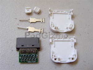
This is when I broke out the PodBreakout Mini that Mike had sent me. It doesn’t have all 30 pins but it has what they call the “most commonly used” pins: 1, 3, 4, 5, 6, 8, 13, 12, 21, 23, 25, 27, 30. 12 and 13 are the serial port, so that’s good. I wasn’t sure what to do about GND though — I’d been using pin 11. I checked with Mike and he said they hadn’t observed any differences between the grounds, so I went with pin 1.
Here’s the final setup:
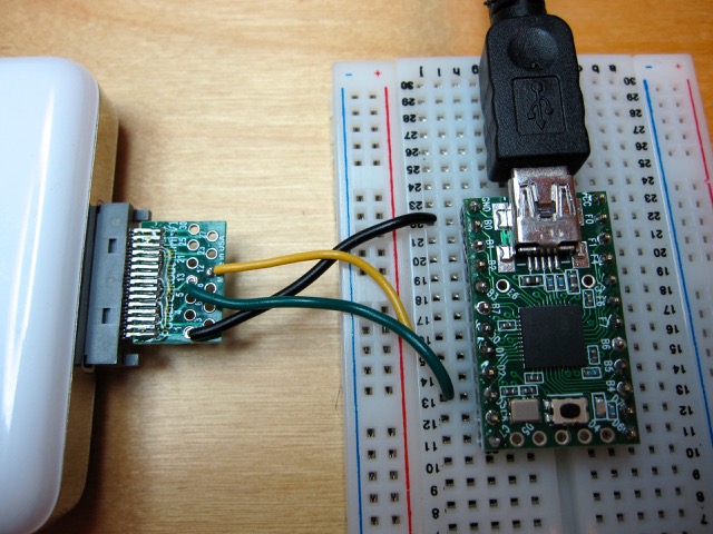
It is a nice compact setup, it only needs three wires (Tx, Rx and GND), it doesn’t need a converter board in the middle, and most importantly it works perfectly!
The PodBreakout Mini’s board fits entirely inside the usual white plastic case (which it comes with), so it ought to be much more robust than the full-size PodBreakout boards I’ve been using up until now, where the wide board is hanging out the back of the connector.
The Teensy seems to be a great value at $18 ($19 if you get the 3.3V regulator to go with it), and the size is nice too. I’m going to start playing around with its USB features when I find some more time.
Thanks again to Paul and Mike for sending me cool things to play with, with no strings attached.
PodBreakout Warning
I’ve had email discussions with a few people who’ve been having trouble replicating my work. They all had v1.4 PodBreakout boards, whereas the two I have are v1.2. So I asked Mike at Kineteka if there was a difference and he said there was:
There is a slight difference in the v1.4 due to a manufacturing glitch.
The boards still work the pinout is just flipped.
The pins are odd /even as opposed to even / odd. see below.
Back side of dock connector v1.2
02 04 06 08 10 12 14 16 18 20 22 24 26 28 30
01 03 05 07 09 11 13 15 17 19 21 23 25 27 29
Back side of dock connector v1.4
01 03 05 07 09 11 13 15 17 19 21 23 25 27 29
02 04 06 08 10 12 14 16 18 20 22 24 26 28 30
So for instance the audio pins 3,4,5,6
PodBreakout Pin V1.2 V1.4
Right Line Out 3 4
Left Line Out 4 3
Right Line In 5 6
Left Line In 6 5
We are working on updating the http://www.kineteka.com/PodBreakout-v1.aspx page to reflect these changes should be up soon.
So if you have a v1.4 board you’ll need to adjust your connections appropriately.
iPod Serial wake up!
I did some digging tonight and the iPod Photo will respond to the remote just fine until the iPod goes to sleep — either explicitly via the “Sleep” menu item, or implicitly because it times out after sitting unplaying for a while. After walking it up, it will no longer respond to the remote. Disconnecting and reconnecting the remote doesn’t help; resetting the Arduino doesn’t help either. Resetting the iPod does cause it to start responding to the remote again — without doing anything at all to the remote or its connection.
As I mentioned, I used this remote for months, but only with an iPod Touch. I don’t have the iPod Touch any more, but I do have an iPhone. I cannot reproduce this behavior on the iPhone. There’s no real equivalent to the older iPod’s sleep, but if I press the button on the top of the iPhone, which shuts off the display and causes the lock screen to appear when the main button is next pressed, the remote continues to work just fine.
So that was with the SimpleRemote_with_Bounce example sketch. I then tried the SimpleRemote_ethernet sketch, since that lets me try other Simple Remote commands interactively. I put the iPod to sleep via its menu and tried sending “play” via my telnet connection to the Arduino running SimpleRemote_ethernet. Again it ignored me, just like it ignored the easy button. I then sent it the Simple Remote “iPod on” command, and voila! It woke right back up and started responding to me again.
So then I modified the SimpleRemote_with_Bounce sketch so it would send “iPod On” just before sending “Play” and it worked! I can no longer reproduce the unresponsiveness after the iPod has gone to sleep.
If you have been using the SimpleRemote or SimpleRemote_with_Bounce example sketches, please consider using the new SimpleRemote_with_Bounce_and_wake instead (yeah, I have no imagination when it comes to titles, but I wanted to rename it). I’ve deleted SimpleRemote and SimpleRemote_with_Bounce from the library on github to avoid confusion.
If you try this and it works — or doesn’t — for you, please let me know.
iPod Serial Talk
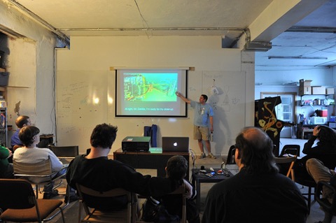
I had the great pleasure of giving a talk about my iPodSerial library at Make:PGH last night. I’ve been a subscriber to Make Magazine since issue one, so this was especially exciting for me. Thanks to those that came out and suffered through my ramblings, to Hack Pittsburgh for hosting, and to the Make:PGH crew for setting it up. I enjoyed listening to Eric Singer’s talk too.
If, for some strange reason, you want a copy of the slides you can grab the PDF version here.
If, for some even stranger reason, you want a copy of the Keynote file just contact me through the captcha link in the footer.
iPod Serial and the Nunchuk
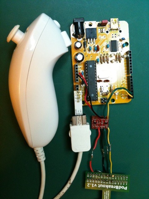
The Wii Nunchuk has a joystick, from which you can read the X and Y axes, a Z button, a C button and the 3-axis accelerometer. I mapped the controls so that: left/right on the joystick is skip forward/backward; up/down on the joystick is scroll up/down; Z button is Play; c button is Ok/Select; and a tilt backward (using the Y axis of the accelerometer) is the menu button.
You could of course map them any way you wanted to.
Here’s a quick video of it in action (the Arduino is off-screen to the right).
iPod Serial and the iPhone
Bad News
I have discovered that I am unable to get Advanced Remote mode to work with the iPhone 3G or 3GS. I had been doing all my recent work on Advanced Remote mode with an iPod Photo so as not to put my iPhone through any pain. It was really hard to test before but I wrote an AdvancedRemote_ethernet example sketch (it's in the library in github) to help with that. Recently I spoke with Ben, who is doing some RFID work with a jailbroken iPhone. He could get his iPhone to receive serial commands but not transmit them, and the key for him ended up being the presence of the 500kOhm resistor on pin 21 - without it his app on the iPhone couldn't transmit to the serial port.
Because Ben had been asking me about it, I tried the Advanced Remote mode on my iPhone 3GS and then my wife's 3G. I was surprised to find that the iPhone sees the commands but it sends back a "feedback" response with error 4. The exact same code works perfectly with the old iPod Photo. At first I hoped this was because I'd removed the resistor on pin 21 - which wasn’t needed for the iPod Photo - so I put it back, but still no luck. Then I thought that perhaps the iPhone is fussier about the value of the resistor - I was using a 560kOhm and it's supposed to be 500kOhm - so I ordered some 500kOhm resistors from digikey. These arrived yesterday so I swapped the resistor, but I saw the same problem. So it looks like the resistor is needed for applications on an iPhone to be able to transmit serial data, but for the built-in iPod application there needs to be either something more than that or something instead of that.
I know the iPhone is incredibly specific about the inputs it sees before it will charge itself through the dock connector, so I'm guessing there's something like that about it wanting to see something on some other pins before it's willing to be controlled via Advanced Remote mode too. It has to be possible because my car does it with my 3GS, and it's the kind where the car has a separate display and can show track information etc, so it must be using Advanced Remote mode. I may probe the cable that comes with my car if I can find some time.
Good News
The Simple Remote mode commands do work with the iPhone though. I wrote a SimpleRemote_ethernet example sketch and was able to go through the menus, change the volume, play/pause, etc. on my 3GS. The initial remote I had in my old car with the Easy button used this approach.
iPod Simple Remote Example
The SimpleRemote_with_Bounce example sketch sends the Play/Pause message when it sees a button is down and sends the “button released” message when it sees the button is up. This is the sketch I used in my own remote.
This sketch uses the Arduino Bounce library to debounce the button. There’s a version that does the debouncing on its own, called SimpleRemote, but it’s more complicated and wouldn’t scale if you were to use it for more buttons.
Let’s take the example sketch line by line (mostly):
Line 7 pulls in the Simple Remote mode header file from the library. You need to have placed a copy of the iPodSerial library in your Arduino IDE’s libraries folder for this to work.
Line 8 pulls in the Bounce library. You need to have placed a copy of the Bounce library in your Arduino IDEs libraries folder for this to work.
Line 10 says we’re going to have our button connected to the Arduino’s digital I/O pin 5.
Line 11 sets the debounce interval to 20 milliseconds, meaning that the button has to stay up or down for 20 milliseconds before the Bounce library will decide that is really up or down.
Line 13 creates our Bounce object, which is what’s going to do the debouncing for us.
Line 14 creates our SimpleRemote object, which is what’s going to talk to the iPod for us.
Line 18 makes digital I/O pin 5 an input, so we can read from it to see if the button is up or down.
Line 21 enables digital I/O pin 5’s internal pull-up resistor. This sounds scary, but all it means to us is that we can connect a button between pin 5 and ground without any other circuitry, which is referred to as an active-low configuration. The means that the pin will read as LOW when the button is down (pressed) and HIGH when the button is up (released). That probably seem backwards but as long as we’re expecting it to work that way it’s not a problem.
Line 23 takes care of setting up the serial connection to the iPod.
Line 28 lets the SimpleRemote object take care of anything it needs to do with the iPod. This needs to be in our loop() function.
Line 30 asks our Bounce object if there has been a change in the state of the button. That is, has the button just been pressed or just been released.
Line 32 checks the new state of the button, now that line 30 has told us the button has just changed state. If the new state is LOW that means the button has just been pressed (since we’re using an active-low button configuration).
Line 34 will get executed if the button has just been pressed. It tells our SimpleRemote object to send the Play command, which toggles the iPod between Play and Pause, just like the physical Play / Pause button would.
Line 37 will get executed if the button has just been released. The Simple Remote protocol requires this so that the iPod knows when the button has been released. Because of this, press-and-hold behaviours of the physical buttons also work through Simple Remote mode. So, for example, if you press and hold the button using this sketch the iPod screen will fade to black after a few seconds, just like it would if you pressed and held the physical Play button.
And that’s it!
If you look in the library at the file SimpleRemote.h you can see the full list of commands that can be sent:
- Play (the one we used in the example, that toggles between Play and Pause)
- Volume Plus
- Volume Minus
- Skip Forward
- Skip Backward
- Next Album
- Previous Album
- Stop
- Just Play (rather than toggling between Play and Pause)
- Just Pause (rather than toggling between Play and Pause)
- Toggle Mute
- Next Playlist
- Previous Playlist
- Toggle Shuffle
- Toggle Repeat
- iPod Off
- iPod On
- Menu
- Ok / Select
- Scroll Up
- Scroll Down
Expanding the example to work with more buttons is pretty simple. Let’s see what it would look like if we added volume plus and minus button support:
iPod Remote Part Deux
4/14/2010 UPDATE: See here if you have a v1.4 PodBreakout board.
I had been using my iPod remote for a few months. It worked well and scratched the itch it was built to scratch. But in December I got a new car with iPod and Bluetooth integration. I also got rid of my despised Blackberry and switched to an iPhone. This meant I no longer needed to use my custom remote, so I placed it lovingly in my electronics drawer and forgot about it for a while.
Recently I was asked if I would present a talk at Make: PGH about my experiences developing my Arduino iPod Serial library. I agreed, and it’s tentatively scheduled for the April meet-up. Someone also sent me an email asking for some help troubleshooting their build of a remote, so I was inspired to dig the remote out of the drawer. I also took a look at the library I’d created and decided that I really ought to finish what I’d started.
I already had a spare logic-level converter and PodGizmo from the original project, so I soldered them together and hooked them up to my Mega. (The Mega is great for testing serial protocol stuff because it has four real serial ports, compared to the one on a regular Arduino. I built the library with debug hooks in it so that I could spit out the protocol data going back and forth between the iPod and the Arduino, and without that it would have been really hard to debug it.)
I discovered that the resistor connected to pin 21 isn’t needed. I also realized that I could use the iPod to supply the low-voltage power to the logic-level converter. This cleaned up the wiring considerably (click on the image to go to Flickr where there’s a full-resolution version):
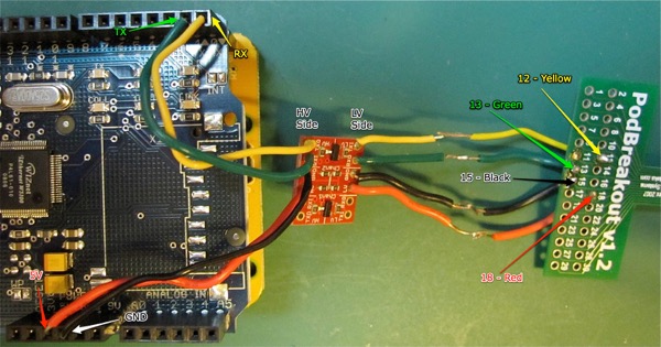
On the left is a Freeduino with an Ethernet Shield on top of it, but more on that later - the point is that you just need 5V, Ground and your Serial TX/RX lines on the Arduino side. The awful connections in the four wires between the logic-level converter and the PodBreakout board shouldn’t be there. They only exist because I tried out the suggestion here to skip the logic-level converter and put a 1KOhm resistor between the Arduino TX pin and the iPod RX pin. I verified with an EE friend that this would be okay and he said:
While not optimal, you should never see a problem with a 1k resistor. On TX_ARDUINO... (not RX_ARDUINO). What you're doing is relying on the protection diode of the iPhone to clamp the Voltage and sink some current. The resistor will do two things. 1) Limit the current possible to send into the iPhone (5V / 1k = 5mA max). Almost all digital protection circuits can handle 5mA for a few minutes at least. Therefore, even if you wire it up wrong, you will be very unlikely to fry anything. 2) Provide somewhere besides the protection diode in the iPhone to dissipate the power (V^2/R = 1.7*1.7/ 1k = 2.89 mW). 3mW isn't a lot of power for a diode, but it will help prevent the chip from wearing out prematurely.
Vih on the ATmega328 (Duemilanove) is 0.6*Vcc when Vcc is 5.0V. This means that the input signal needs to be above 3.0V to be guaranteed to be seen as a "1". There's usually a bit of guard-band on that spec. However, I would NOT put a resistor on the iPhone output to the Arduino (RX_ARDUINO). If you did, you'd start to see bit errors at higher bit rates. At 9600 baud, you shouldn't see anything unpleasant on either side of the bus.
As he said, it didn’t do any harm to my iPod, but unfortunately I was unable to get any communication to work using this method. I tried it a few times, even with just the Play/Pause sketch, which requires no response from the iPod, without luck. It could be that I did something wrong though. The logic-level converters are under $3 so I’m okay with continuing to use them.
Back in September I had two example sketches included in the library: a Simple Remote Mode one that did play/pause, which was what I was using in my car; and a proof-of-concept sketch for Advanced Remote Mode. This went with the just-proof-of-concept Advanced Remote mode support I had implemented. Over the last few weeks I have added full support for Simple Remote Mode, which was pretty easy, and near-full support for Advanced Remote Mode (no picture block support), which was a lot more complicated. I also refactored the library code because it needed to be done, and that sort of thing makes me happy.
I have been adding example sketches as I go, and I will talk about those in follow-up articles.